Material Testing Machines (3/19/2021)
4-Point Bending Tester
3-Point Bending Tester
I took a materials science class this semester with an accompanying lab, and for some of the labs I needed to perform 3- and 4-point bending tests on materials to characterize their mechanical properties. Instead of doing things the easy way, I decided to design and build a set of machines for these tests. Each lab was two weeks long, so there was a bit of a time crunch but they ended up working very well and I got excellent results for my lab.
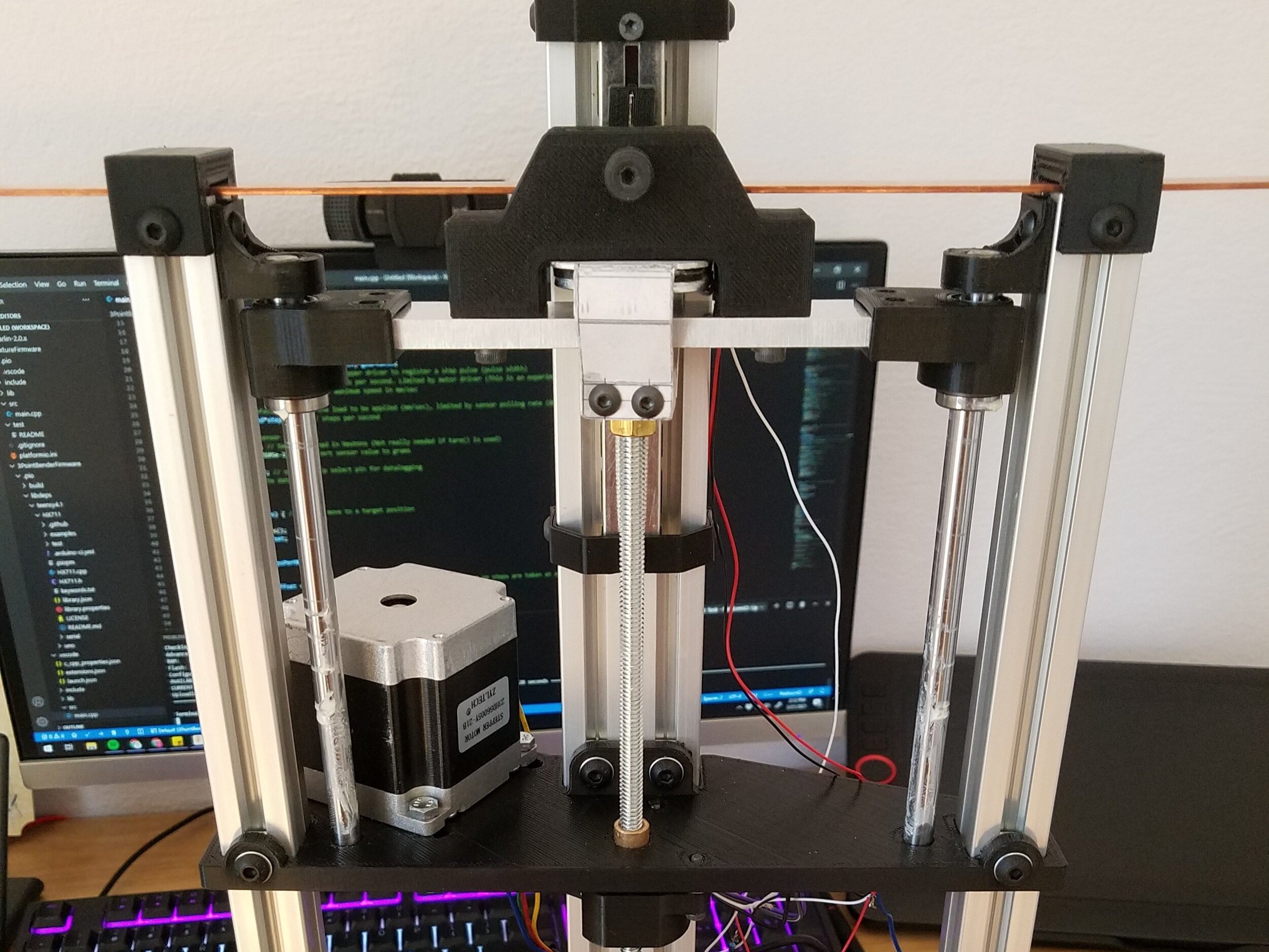
For the first machine, I 3D printed almost all of the parts because it was fast, cheap, and easy. It was a 4-point bending tester, and since the mechanical design wasn’t too crazy I won’t spend a ton of time going over it. It was made with two linear rails made of hardened steel with a chrome coating that I had lying around as spare parts from an old 3D printer, as well as a lead screw and nut from the same printer. The lead nut is held captive and gets turned by a stepper motor, which moves a platform up and down to apply force to glass microscope slides. The force is measured with a load cell via an HX711 and the position is obtained from dead reckoning, with both measurements periodically printed to a serial terminal. Everything was controlled by an Arduino Uno, which became a problem at higher speeds due to its relatively low clock frequency, more on that later.
The software for the 4-point bending tester was written in C++, and had some cool features. Aside from the data being printed to a serial terminal, it also had brittle fracture detection so it could automatically detect sharp decreases in the applied load and then retract to give room for the broken sample to be removed and a new one to be put in place. The code to drive the stepper motor left a lot to be desired though; rather than using a prewritten library I wrote some code to provide step and direction pulses in between load cell readings, but this didn’t work too well. The motion was somewhat jerky and no matter how much tuning I did the motion couldn’t be completely smoothed, so I decided to call it good enough because I was running out of time. Overall, a week and a half of work ended up allowing me to test multiple samples rapidly, with a single test taking roughly a minute. There wasn’t much times saved overall, but this was still a good experience.
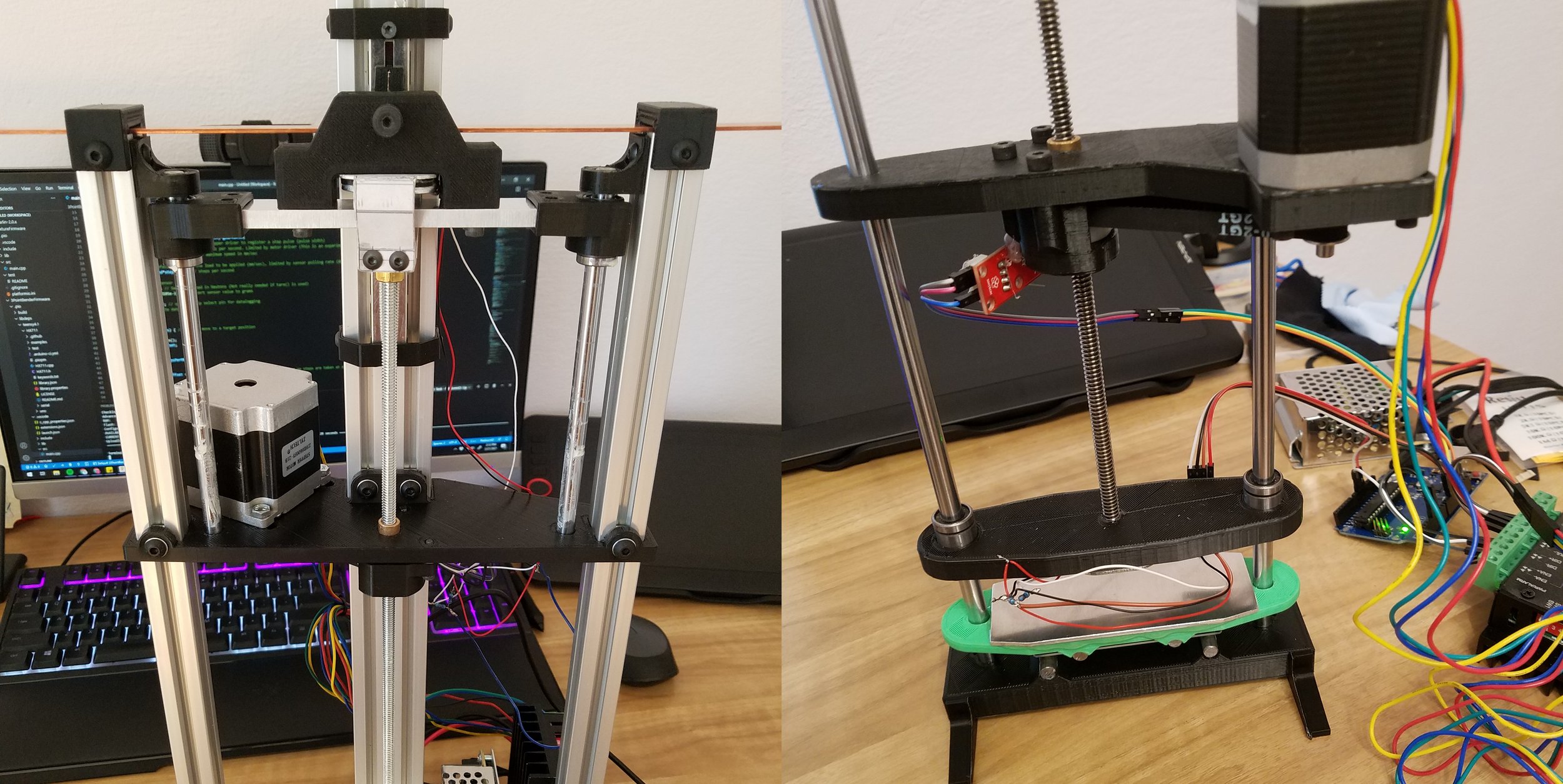
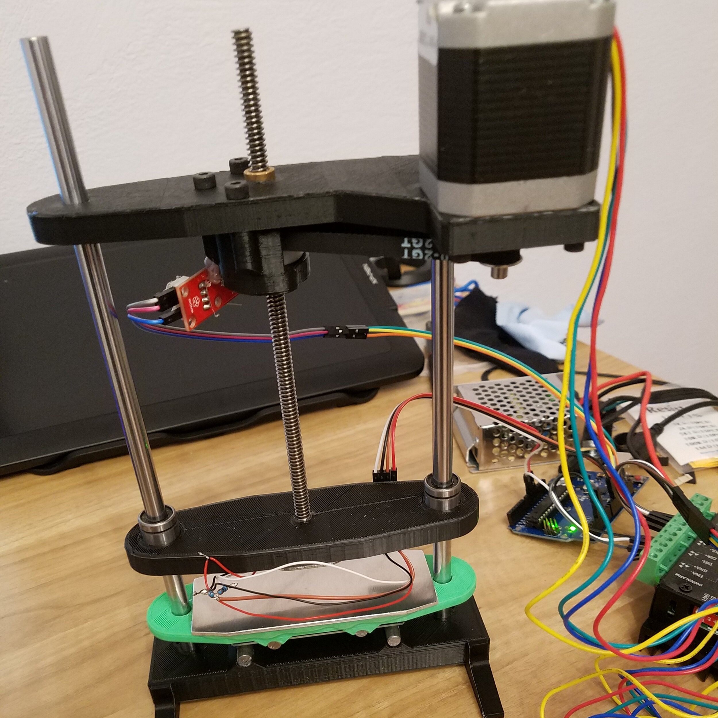
For the 3-point bending tester, I decided to start a bit earlier and took what I learned from the previous attempt to make a machine that was actually good. It turned out to be good enough that my advisor asked me to send design files and code so the university could make some for future classes. I also plan to make this machine open source once I clean up the designs a bit and make a few improvements.
I’ll start again with the mechanical assembly. The provided material samples were fairly long and thin, so rather than cutting them into pieces and load them in the bottom of the machine like with the last one I decided to just load them on the top of the machine, so the layout is reversed from both the previous machine and the conventional machines. The main structure of the machine was made with aluminum extrusions that I had as extra parts from my most recent 3D printer build. They were screwed to a 6mm base plate made from mic-6 aluminum. This was overkill, but I had extra material from the build plate from my printer so I figured I’d use it. For the linear motion, I used more spare chromed rods like in the 4-point bender, and a length of threaded rod to move the load cell and loading pin up and down. I also used a larger nema-23 motor to allow for more force. For the other parts, most of them were 3D printed but a few were made from 6061-t6 aluminum and there was a bent part made from 5052-h32 aluminum to apply force through the load cell to the loading pin. The ends of the material samples were clamped in place, and the loading pin was a shoulder bolt.
For the electronics in this machine, I upgraded things a bit. Instead of using an Arduino Uno, I opted for a Teensy 4.1 due to the significantly higher clock frequency and the integrated micro SD card slot for data logging. I also added a linear potentiometer attached directly to the loading pin to measure the real deflection independent of any flex in the machine itself, readings for which were made with a separate 12 bit ADC communicating with the Teensy via I2C. The load cell was the same type as in the 4-point bender, but I increased the sample frequency of the HX711 to 80 HZ from 10.
The software is where things get fun - it’s roughly 500 lines of code (which really isn’t a lot, but there are a lot of features packed in there) - and an absolute mess. I think a bulleted list is probably the easiest way to list all of the features, then I’ll go through them one at a time.
Command parsing via serial communication
SD card presence detection
SD card data logging
Rapid and slow moves
Dead reckoning and real position moves
Force target controlled moves
Sanity checks in all movement commands
“Multithreading” through precise timing for reading sensor data and driving the motor
Fully configurable settings for motion and calibration
Command line parsing
There was a series of commands similar to G-Code that could be used to give instructions to the machine. Whenever a command was received, it is parsed to determine if it’s garbage or one of the following commands: rapid move, target position move (slow, with or without data logging), target force move w/ data logging, and close the data log file so the SD card could be removed. Once a command was parsed, the relevant arguments were stripped out of it and the corresponding method was called.
SD Card Presence & Data Logging
The machine wouldn’t start without an SD card present for data logging. This also works for locked cards, so if a card is read-only it wouldn’t work either. It then logs the data to the SD card as it is read. Time, force and position were all logged to the card whenever logging was active so it could be plotted or analyzed later.
Movement & Multithreading
Multithreading is a bit dishonest, but in methods where the machine was moving and was logging data everything was timed in order to allow the motor to take steps in between data collection cycles. The potentiometer was read at the same time as the load cell so there wouldn’t be more data entries from one sensor than the other. This was basically a while loop that counted elapsed microseconds to decide when things should happen, so it’s not real multithreading but it does allow multiple tasks to happen somewhat simultaneously.
To drive the stepper motor, similarly to the 4-point bender I wrote a few methods to take steps and switch directions. This allowed other things to happen in the “thread loop” when the motor wasn’t taking steps, because all of the libraries I found couldn’t be run simultaneously with other tasks. I did try to add acceleration but ultimately ran out of time and had to actually run the experiments.
Configuration
The machine can be configured at compile time through a separate header file. The things that are configurable in this file relate to stepper driver timings, motor steps per unit, load cell calibration, potentiometer calibration, and default speeds. It was just more convenient to have config stuff in a separate file than in the C++ code.