Hopper Mount Brackets & Sheet Metal Bending (9/25/2018)

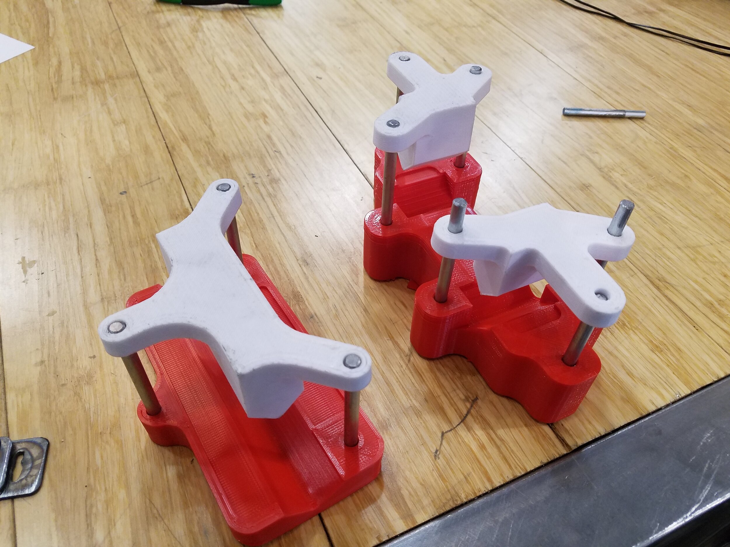
One of the finished brackets before it was painted

CAD model of the crude bending die
While putting together a presentation about some research a team I was leading had done to give to a plastic recycling startup (I actually ended up getting a job offer there a few months later), they were simultaneously having machines built based off of the Precious Plastic V3 designs. The company they contracted to make the machines reached out to ask if I could help make some parts for them since they were on a time crunch, and I agreed. I went out to their facility, and after some discussion I helped with a few different things, and made a few parts, one of which was some brackets to hold a hopper on the plastic extruder.
We laid out what they needed to do and how they should fit, and after I took some measurements and pictures for reference I went home to design the brackets. This didn’t take too long, they weren’t too complicated, but I also needed to figure out a way to actually make them. 3D printed tooling was the obvious choice to me, since it needed to be cheap and made quickly, and they only needed a few brackets, so the tools didn’t need to stand up to a lot of abuse .
After playing around with a concept to press some crude dies together that would guide the sheet metal into place, I realized that the printed layers would probably delaminate, at best just wasting a day or two to redesign and print new tooling, and at worst wasting material by deforming it. So instead of reinforcing the die to try to prevent it from breaking, I started a redesign from scratch.
Keeping the same bracket design, I thought of other ways to bend the brackets into the desired shape, and realized I could replicate the process of a press brake fairly easily. With that goal, I took a flat pattern of the bracket, and designed tooling to bend the flat sheet metal. To guide the punches into the correct place and keep them aligned, I added some steel shafts embedded in the dies for them to run along. After checking that there was enough clearance for everything to fit together, and that I had taken into account the metal’s springback, I started printing the punches and dies.
Both the punches and dies were printed in PLA, since it has very good compressive strength and is quick to print. The parts were all printed with a shell thickness that varied between 2.5-5mm depending on the forces, and with an infill density of 50%. Notably, higher infill density doesn’t always correspond to stronger parts, but since the parts were all going to be loaded in compression, the higher density provided a lot of additional strength.
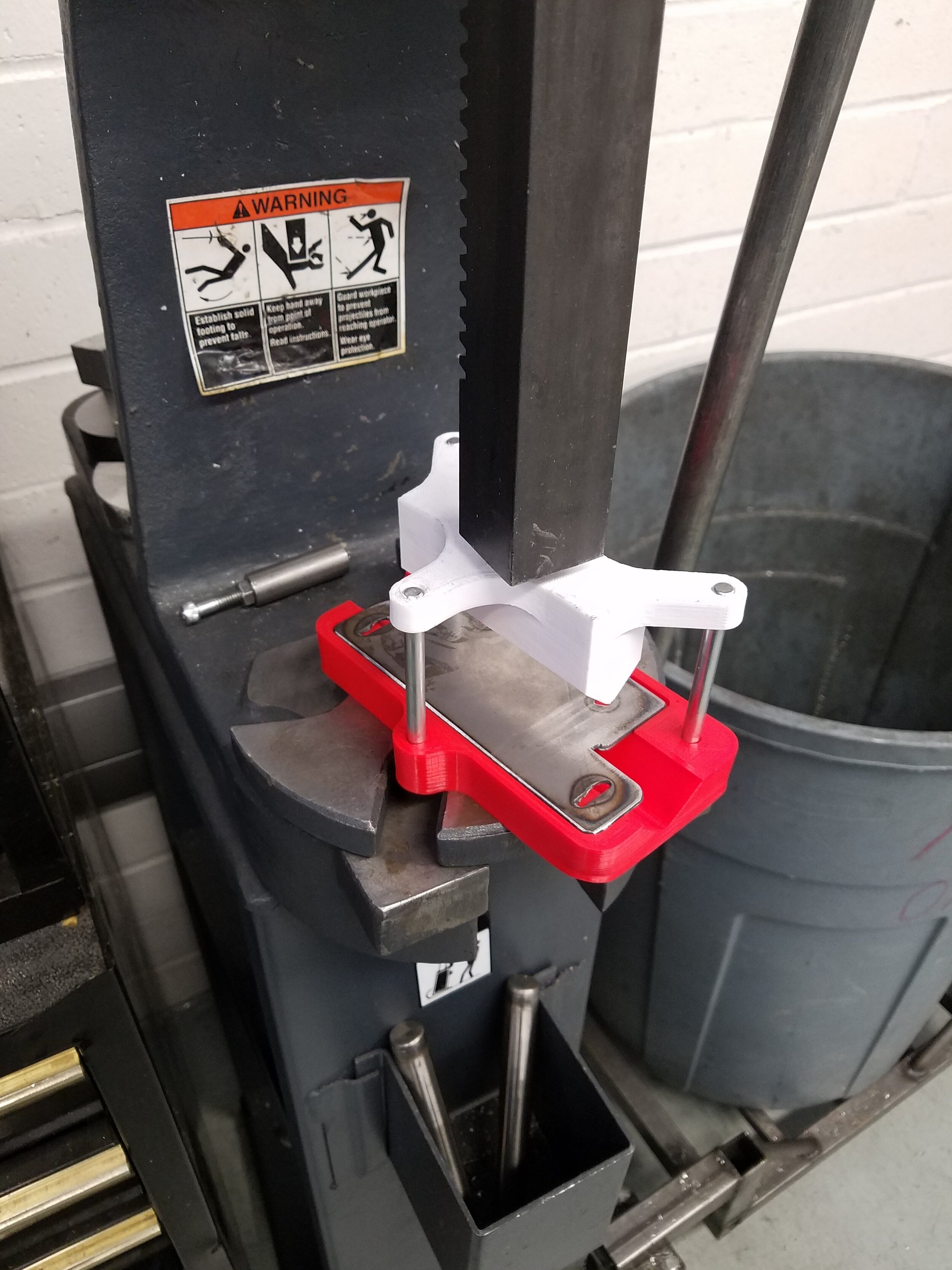
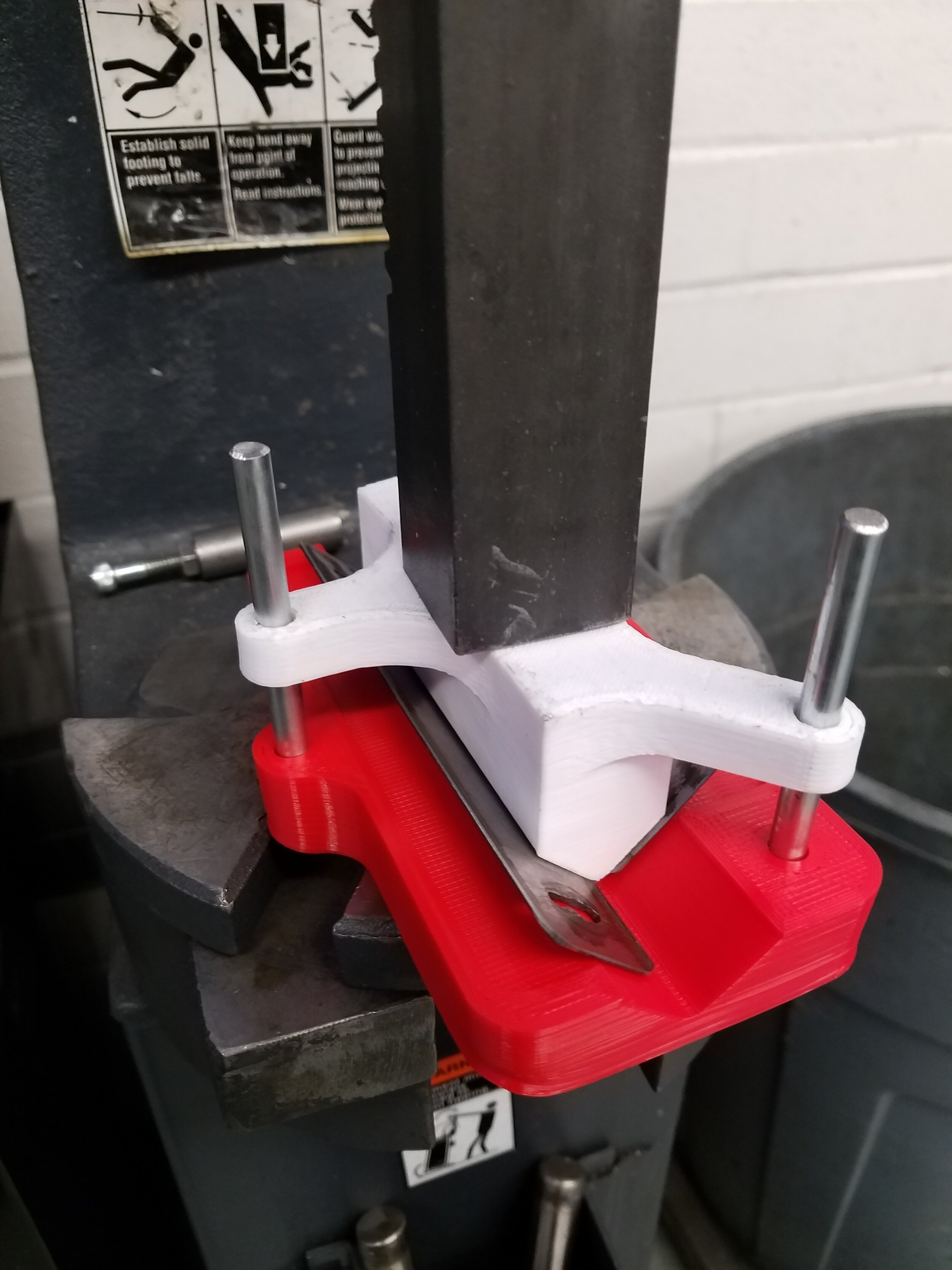
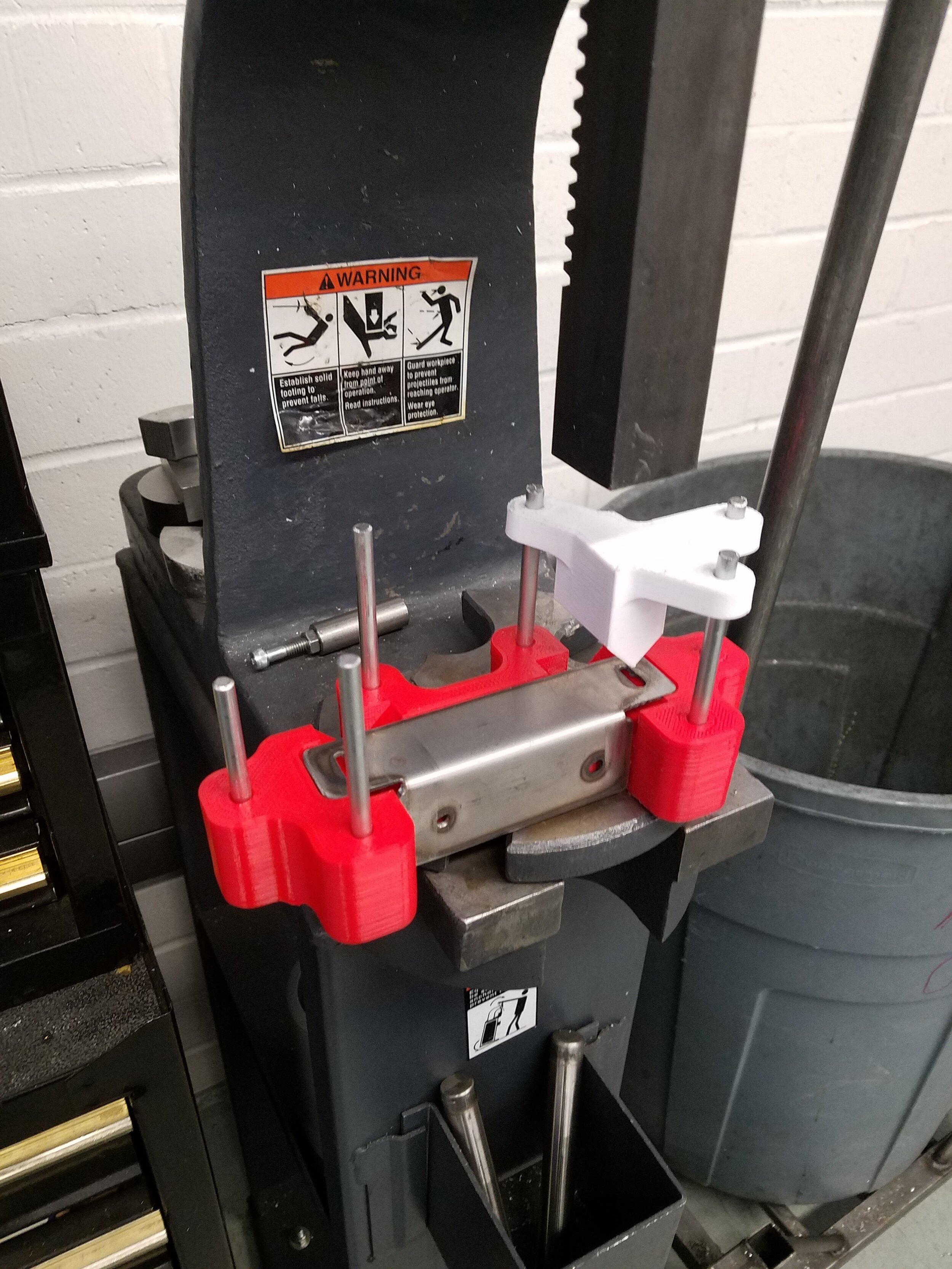
The brackets were made from 16ga steel sheet, and the flat parts were made on a CNC plasma cutter. After they were cut out, I cleaned them up with a belt sander and a flap disk on an angle grinder before placing them in the dies to be bent. To provide enough force to bend the steel, I used an arbor press. Surprisingly, the brackets bent easily with very little force, and the brackets came out better than I expected.